In solidworks, I need to get the coordinates of the bend line end points after using ExportToDWG2.
I can get these coords in solidworks environment but once the face is exported into dxf, they change. because for some reason solidworks rotates the face and coordinate systems in dxf file do not match that of solidworks. how can i do this?
1 Like
That export remains somewhat of a mystery. It creates a new drawing in an invisible document, adds a flat pattern, exports it and closes the drawing. Sometimes it indeed rotates the view, I don’t know why or when.
What are you really trying to achieve?
1 Like
I’m throwing darts in the dark here but I think there might be logic that attempts to rotate the face so it coincides with a standardized coordinate system for the DWG format. I’m wondering if this has anything to do with the normal direction of the face itself in SOLIDWORKS. Thoughts?
@Hamed if you export it to DWG and then to DXF from another CAD software does it still happen?
This is a very SOLIDWORKS-specific question, so how is this relevant? I’m not trying to be snarky here, just trying to understand your thoughts.
Well, Solidworks might be doing something weird in the DXF conversion, so possibly exporting it to a dwg and then using something else to convert it may work out the issues. I am unsure if this is happening to all files or not but a feature may not be converting properly directly to DXF for some reason or another.
Exporting to DWG and DXF is done with the same feature that builds a drawing in the background. So I expect the results to be identical.
yes but the data would be handled differently. due to it being a different format and maybe there is something in the data that dxf doesn’t like for its format.
I’ve asked this from solidworks but have received no response from them yet.
I know that this function actually creates a drawing then inserts a blank view and then makes the view and then saves it as dxf or dwg. (Solidworks couldn’t be slower than this)
I listened to view creation events and got a view that was called “flat-pattern” but there was no ModelDoc2 object in it (hence I think it uses sketches)
I need this to detect bend lines in the dxf file that’s all, if you have another solution to detect them let me know please
So basically what you are trying to get are the coordinates of the bend lines in the coordinates system of the DWG, correct? Can you attach an sample drawing and your code so I can work on this?
I’ve been playing around with this just to see if I can figure out what’s going on. So far, I’m able to use events to determine when a drawing is created. From there, I can get the drawing and view and use the following code to get the bend line coordinates in the drawing view.
From there, I am having a difficult time determining what is going on. SW treats this next step the same way as if the user selects a view on the drawing and then chooses to Save As DXF. There is some coordinate manipulation that happens from the drawing view to the DXF behind the scenes and I have not been able to wrap my head around it.
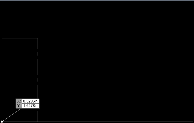
I used the DXF to try and work backwards to see if it was apparent what the coordinate system was doing and I haven’t been able to. Maybe one of you has an idea.
Things I know:
- The location of the view doesn’t matter with respect to the sheet, therefore the sheet size/format doesn’t matter
- The offset of the origin differs when geometry changes so the offset isn’t a hard coded constant
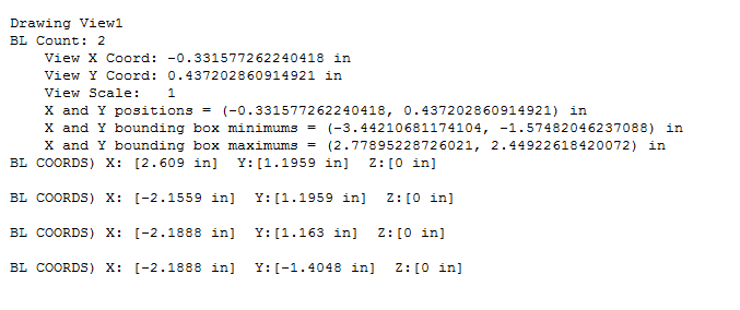
Code to get bend-line coordinates once you have the view object:
    If Not swView Is Nothing Then

        Dim blCount As Integer
        Debug.Print swView.GetName2

        blCount = swView.GetBendLineCount
        Debug.Print "BL Count: " & swView.GetBendLineCount

        Dim vBendLines As Variant
        vBendLines = swView.GetBendLines

        Dim vBendLine As Variant
        Dim swSketchSegment As SketchSegment

        For Each vBendLine In vBendLines
            Set swSketchSegment = vBendLine
            Dim swLine As SketchLine
            Set swLine = swSketchSegment

            Dim swStartSketchPoint As SketchPoint
            Set swStartSketchPoint = swLine.GetStartPoint2
            Dim x As Double
            Dim y As Double
            Dim z As Double

            x = Format(swStartSketchPoint .x / 0.0254, "#,##0.0000")
            y = Format(swStartSketchPoint .y / 0.0254, "#,##0.0000")
            z = Format(swStartSketchPoint .z / 0.0254, "#,##0.0000")

            Debug.Print "X: [" & x & " in]  Y:[" & y & " in]  Z:[" & z & " in]"

            Dim swEndSketchPoint As SketchPoint
            Set swEndSketchPoint = swLine.GetEndPoint2
            x = Format(swEndSketchPoint .x / 0.0254, "#,##0.0000")
            y = Format(swEndSketchPoint .y / 0.0254, "#,##0.0000")
            z = Format(swEndSketchPoint .z / 0.0254, "#,##0.0000")

            Debug.Print "X: [" & x & " in]  Y:[" & y & " in]  Z:[" & z & " in]"

        Next

    End If
Hmm sounds promising! Which event did you subscribe to?
I think you’re gonna have to use matrix transformer to get coords from model environment through drawing view, Cadbooster has a good blog post about it :
1 Like
I have used that article from @PeterBrinkhuis as reference quite a bit over the last few weeks with a separate project. It’s very helpful in its explanations.
The API code that I have selects the coordinates on the drawing, so the manipulation of the values from model space isn’t needed.
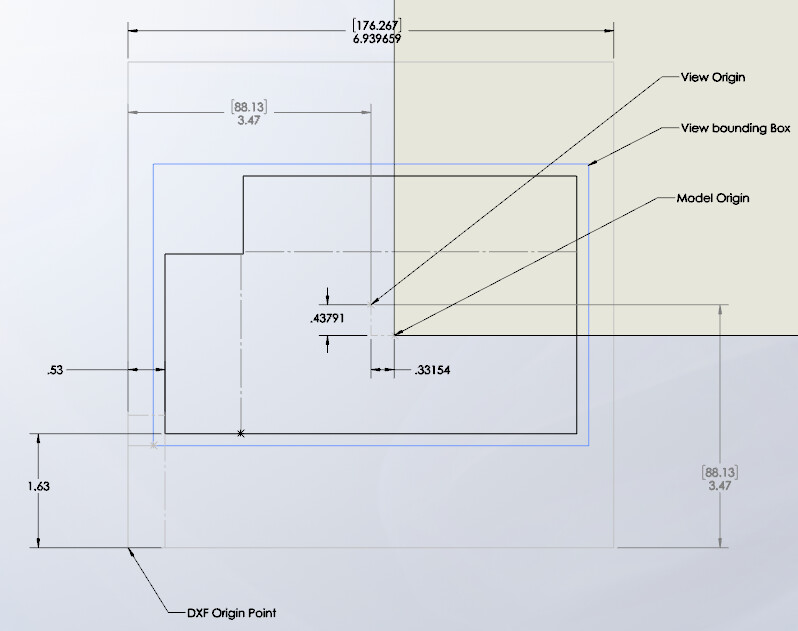
Saving as DXF from a model appears to do the following:
- Creates drawing
- Inserts view of flat pattern with model origin at the drawing origin
- Selects view and performs Save As with the DXF extension selected
The third step is the one where the drawing coordinates are manipulated to the DXF coordinate system. I cannot for the life of me figure out how the coordinate system origin is selected for the DXF file.
May not be related to your needs but make sure that data aligment values are all set to 0 else the exported view rotates.
2 Likes
have done that but unfortunately i get the same result.
Did you ever solve this? I’m trying to do the exact same thing and running into the same coordinate issue
I am not a regular user of Solidworks, so not sure if this is a correct solution.
- Create a flat pattern view in a Solidworks drawing
- Add required dimensions in the view.
- Export this view to dxf.
hi,
can someone explain how we can get these coords in solidworks environment thru API from part modeling interface
Please post a separate question!